CASE STUDY

CASE STUDY

CASE STUDY

Title:

Title:

Title:

From Vectorworks to Stage Layout

Short Film

Short Film

Short Film

Short Film

Cinematographer

Franklin Ricart

Stage Rigging

Tips & Tricks

Overhead Rigging

KEY GRIP

Brendan Riel

Overview

Industry:

Videogame

Location:

Atlanta

Grip Package:

Cinder 5 Ton Grip

Shoot Days:

3

the crew

Gaffer:

Gabe Pippas

Best Boy Grip:

Carlos Mancilla

Grips:

Adam Patterson, Bryan Lee, Jim Recznik, Allen Robinson, Lance Flowers, Tim Chapin, Wes Ahl, Paul Yeager, Wes Stanton

Designing in 3D

I used to be a pen and paper guy but have recently decided to keep up with the times. Pen and paper is great - but it makes changing things a little harder. You have to re-draw your layout every time the gaffer wants to increase the size of your softbox or change the orientation of your lighting. When your softbox size changes now you have to re-draw your truss skeleton again to make sure you’re quoting out and ordering the correct components. I would end up with pages of variations as we progressed through the pre production process. In a way it acted as good documentation and was still there if we wanted to go back to a previous setup. But it wasn’t the most efficient.

I find this whole planning and designing process to be streamlined in 3D. Shifting around components and saving versions is a lot faster than drawing out iterations on paper. Plus you get the bonus of being able to visualize things in 3D space. Your run of blue screen lights on truss may seem good 5’ away from the blue on paper but in 3D you might see that an 8’ distance might work better.

I design layouts in Vectorworks Spotlight. It’s the industry standard for plotting truss and motors and laying out your builds. You can do a multitude of things in Vectorworks - model your stage and overhead rigging points, plot truss and motors, attach lighting instruments to truss, design seating and stage layout, design softboxes and rigs attached to lifts, and much more. This only scratches the surface of what is possible in Vectorworks. There are so many ways to work with data within the program. With lighting you can assign fixture addresses and play with DMX. With truss you can see hanging structure load totals and count up individual pieces for proper pull lists.

All this Vectorworks capability comes with one small setback - the leaning curve is steep.

Let's break down how I integrated Vectorworks into my pre production workflow for a project I worked on.

3D render of truss and motors on stage

Vectorworks Functionality

Plot Truss & Motors

Plot truss and motors in 2D overhead view for easy overhead layout. Top/plan view utilizes symbols to represent different components.

Visualize in 3D Space

Trim heights, visualize your lighting and take in the scope of your setup. 3D visualization is a good way to see relationships between objects and their distances.

Export Drawings

Create views for certain layers and export them to drawings. Take measurements, make annotations. Hide and show different visible layers within the classes and layers panels.

The Process

This job was a promotion for a live action video game. My 3D drawings for this job were pretty rudimentary. That’s the beauty of it - you can choose how detailed you need to go which is a direct correlation for how much time you have to put into your project. The goal of my layout for this job was to accurately plot my rigging points for dead hangs and lay out my truss and motors based off the stage perms. I wanted to be able to walk into the pre rig with an accurate representation of rigging and motors points and take real world measurements based off those drawings.

The whole layout process is so much more streamlined if you can either work off a stage diagram PDF or if you can work from a 3D model of the stage itself. The latter rarely happens. Luckily for this job I had a PDF of the stage overhead. What I’ll first do when working on a new layout is import the stage layout PDF into Vectorworks. Most stages should have engineering reports, but not all do. If they don’t have an engineering report for load capacities then I wouldn’t want to hang anything on that stage anyway. If they do have an engineering report for load capacities but no stage diagram then you need to go there yourself to take measurements. Don’t forget your tape measure and your point laser.

After importing the PDF I resize it to match the real world dimensions with the Vectorworks dimensions. From there you outline the stage perimeter with walls, integrate doors and any other details you need within the structure, and lay out your overhead rigging points. The engineering report usually tells you what the perms are constructed with. You can easily select the material type and size for these beams in Vectorworks when drawing them in. The whole reason for building this all in Vectorworks is so that you can have an accurate representation of your overhead points. You won’t have an accurate representation of your distances in 3D space unless you either resize your PDF upon importing or build from scratch to size. During this stage I like to be as detail-oriented as possible. 2” off on an overhead beam may ripple down through the rest of your rigging points and then they will all be off. You step on stage to rig and your whole plan is thrown in the trash. You’re left scratching your head wondering what went wrong as your guys head out for their second coffee break of the morning.

Once you have your stage and overhead points modeled, save it all as a separate file in case you ever go back to that stage. Start building a library so you’re prepared for the next job at that location.

Next I will integrate the set layout. Art may be able to send over a 3D design file that you can import. I love this option. When a 3D set design isn’t available I’ll most often just rudimentarily lay out rough areas for set sizes.

Truss layout is next. In Top/plan view I’ll start dropping in truss and laying out components over a spatially accurate environment of both our stage and set(s). It’s super important that in the stage build process you accurately sized your build - this is crucial for measuring and spacing out your build. If you don’t accurately size your build then your plots won’t mean a thing when you create a drawing and measure out your rigging points.

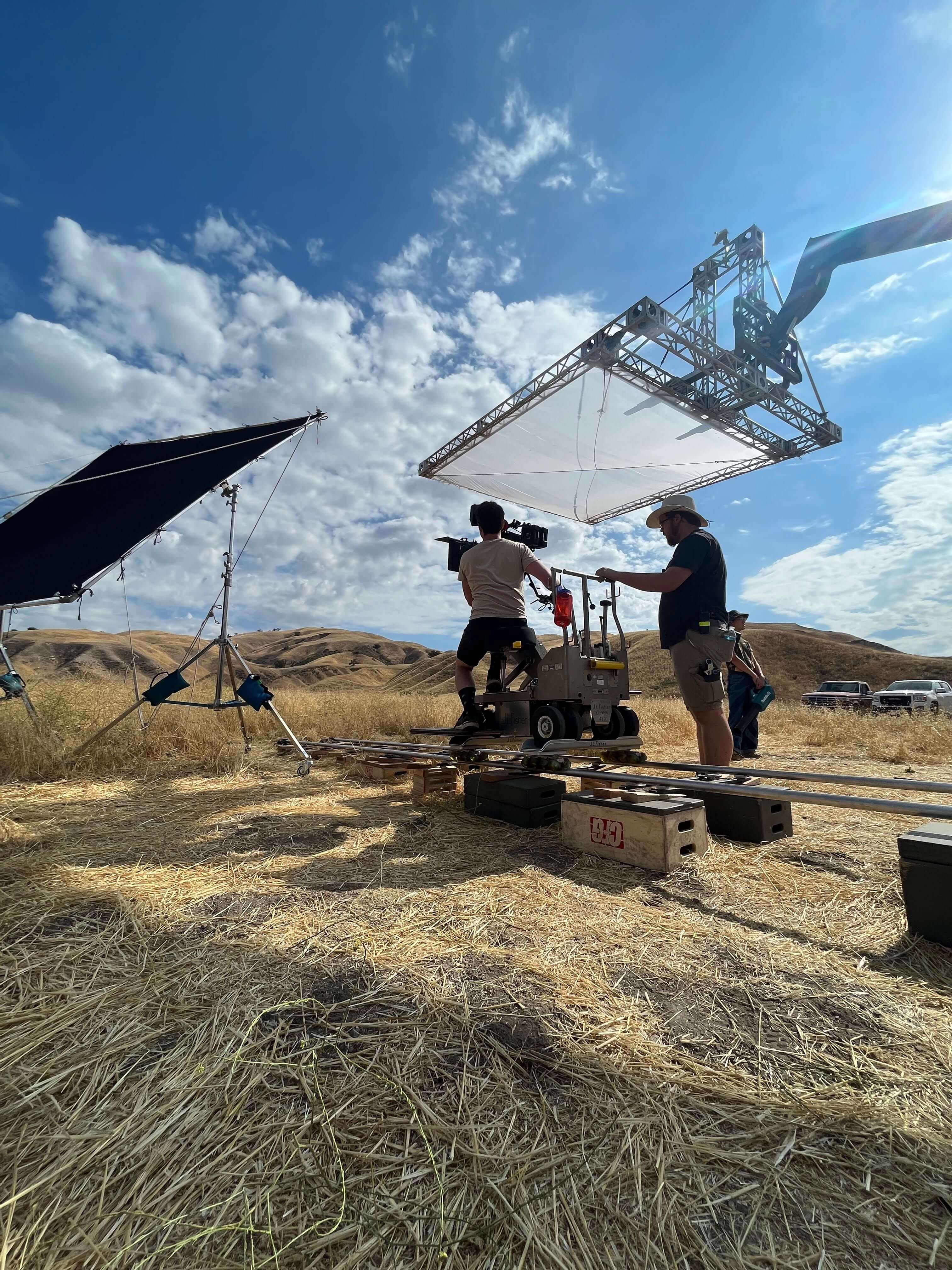
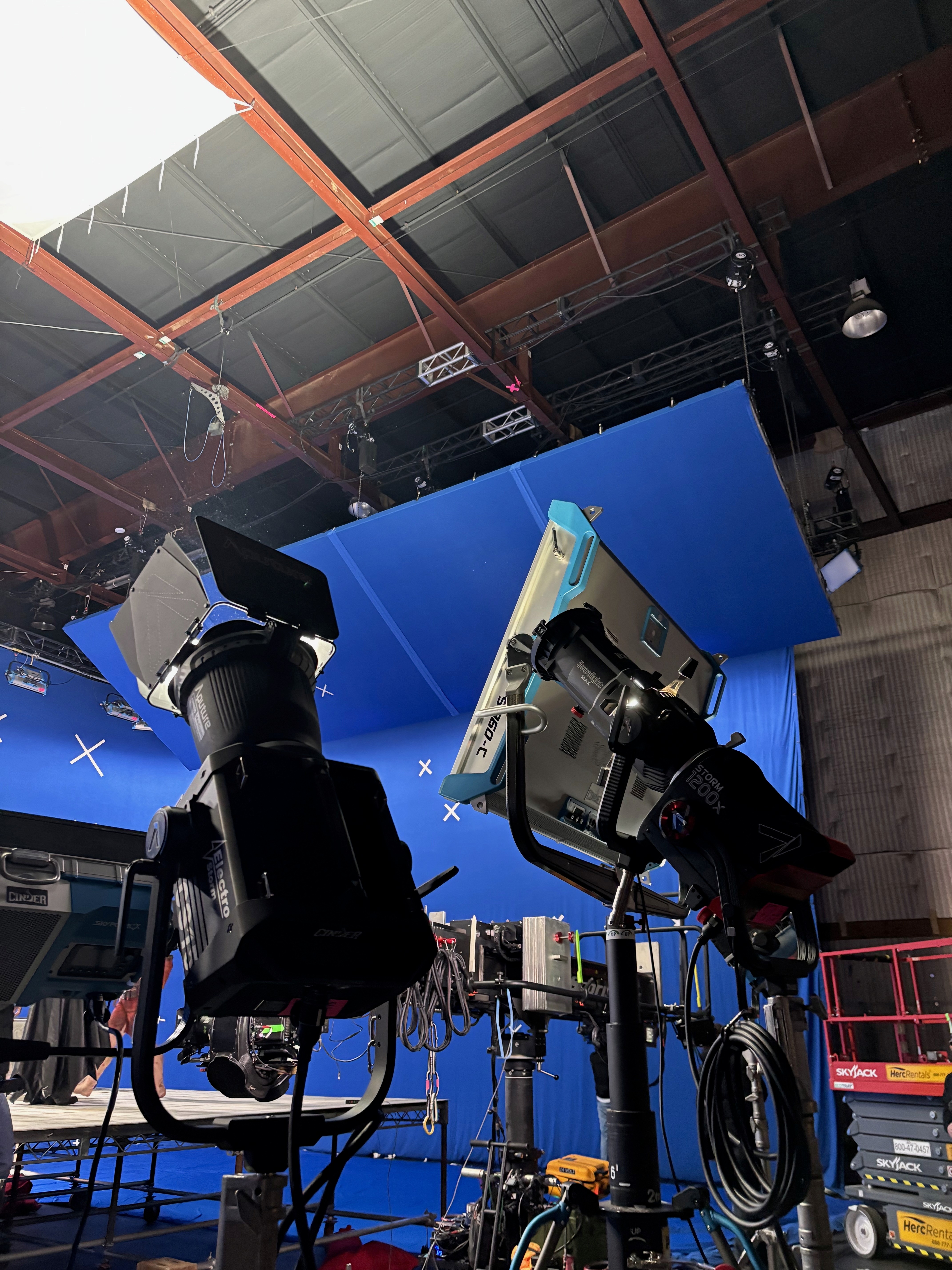
For this job specifically, we knew that we wanted a 30’x100’ blue screen to wrap around the set on some truss and motors. The set design was simple - everything was going to live on either a 20x40 rolling steel deck platform 4’ tall or a smaller rolling steel deck platform. We would have adjustability for both platforms on the day depending on best positioning.

Gabe our gaffer requested 8’ distance away from the blue screen for his blue screen lights.

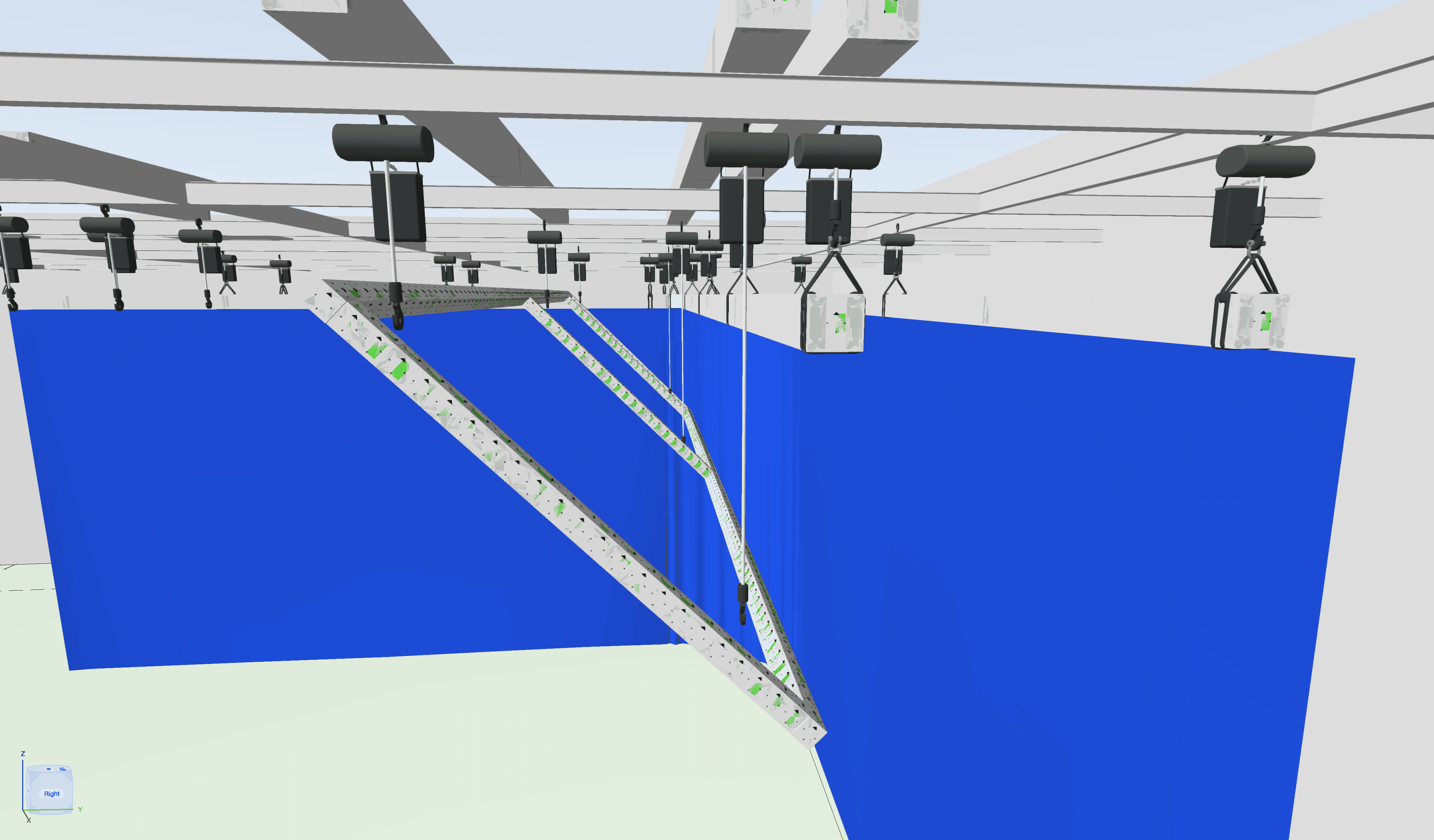
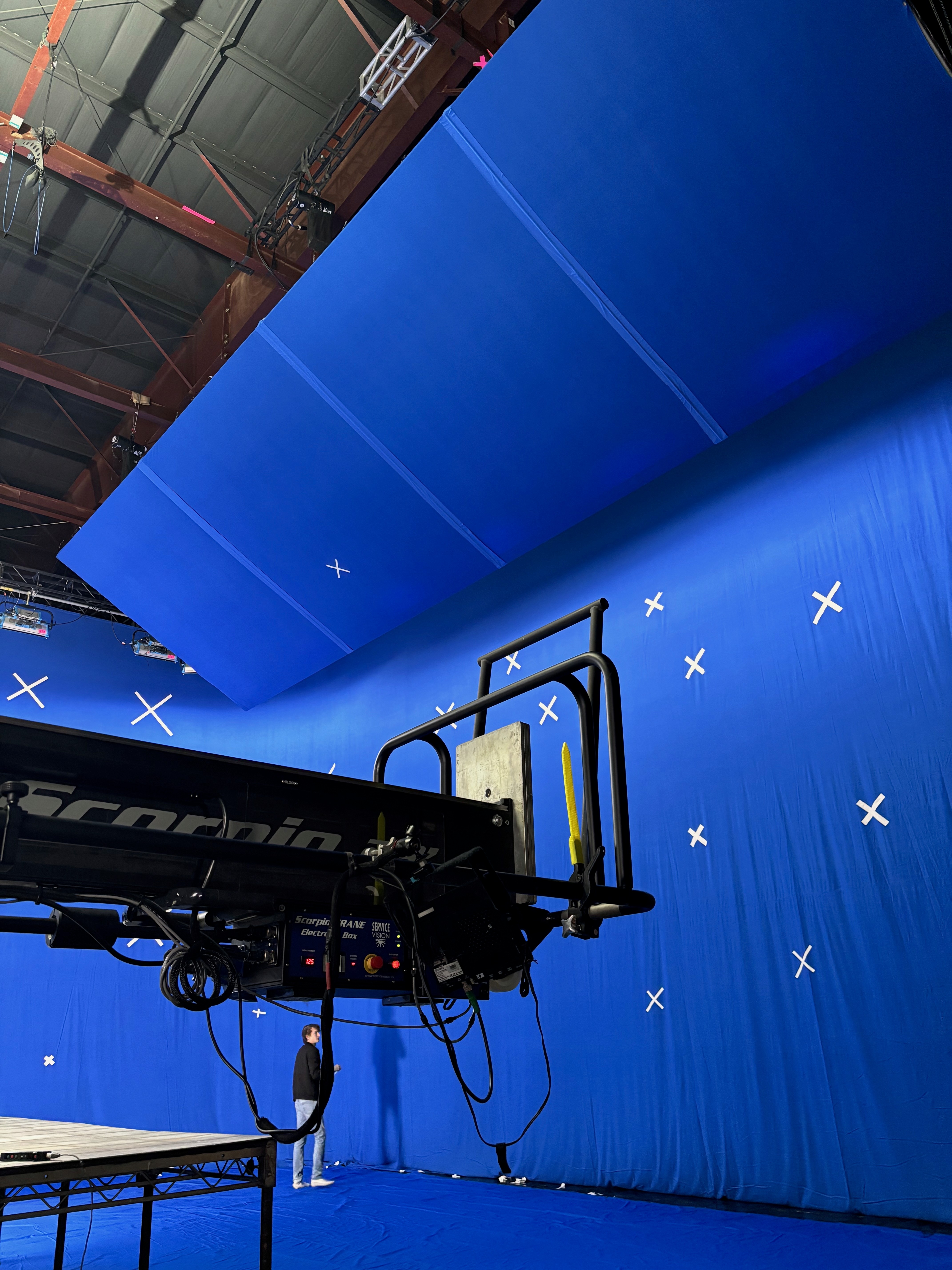
Frank, our DP, wanted to be able to get some low shots looking up at Batman. The 30’ tall blue screen wasn’t going to cut it. We ended up flying a 12’x40’ blue frame made out of Modulus-X truss in front of our 30x100 blue and its accompanying lights. The blue hid the lights behind it and extended our blue screen area up further, making these low angle shots possible. It was important for me to map out this flying angled blue screen in 3D space for a few reasons:


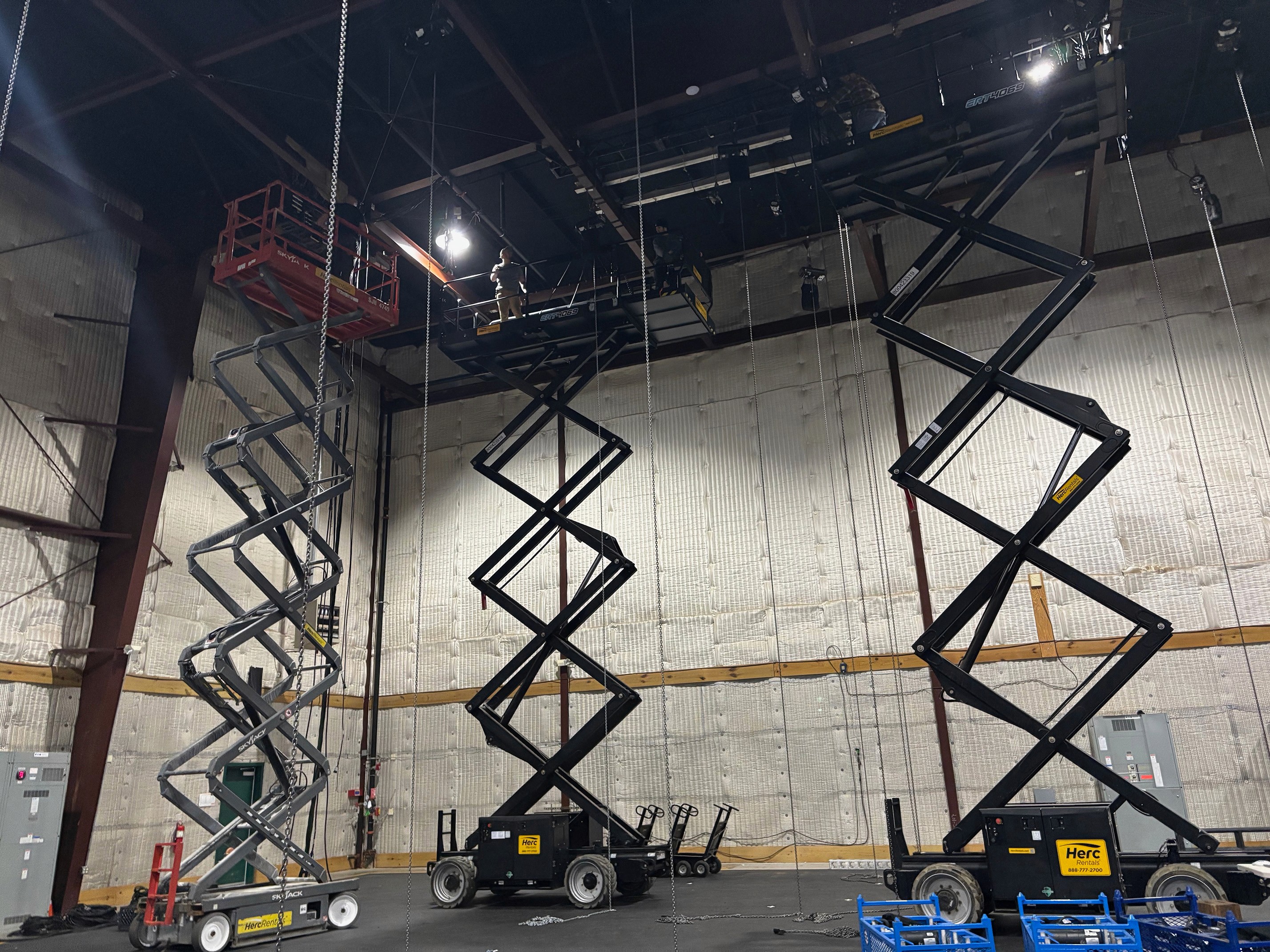
  1. I could see where we could fit motors in overhead within all our other motor points

  2. If I needed to adjust the motor points for the flying blue frame because of space constraints I could then adjust the flying frame rig itself to make sure we have available rigging points where the motors needed to attach

  3. Since the 12’x40’ blue frame was angled, I could precisely see where my pick points on the frame needed to be so we can get the right angle while keeping the motor chains vertical

This type of visualization is hard to achieve with pen and paper! The layout and design work in prep paid off massively. We walked in on the day and went right to rigging without a hiccup. We definitely would not have made our day without a fully fleshed out plan for where to hang our motors and pick points.

***Note: I was working with 2D symbols in this file for ease of use but if you work with a truss object you can more clearly visualize the truss and its shape in your 3D environment.

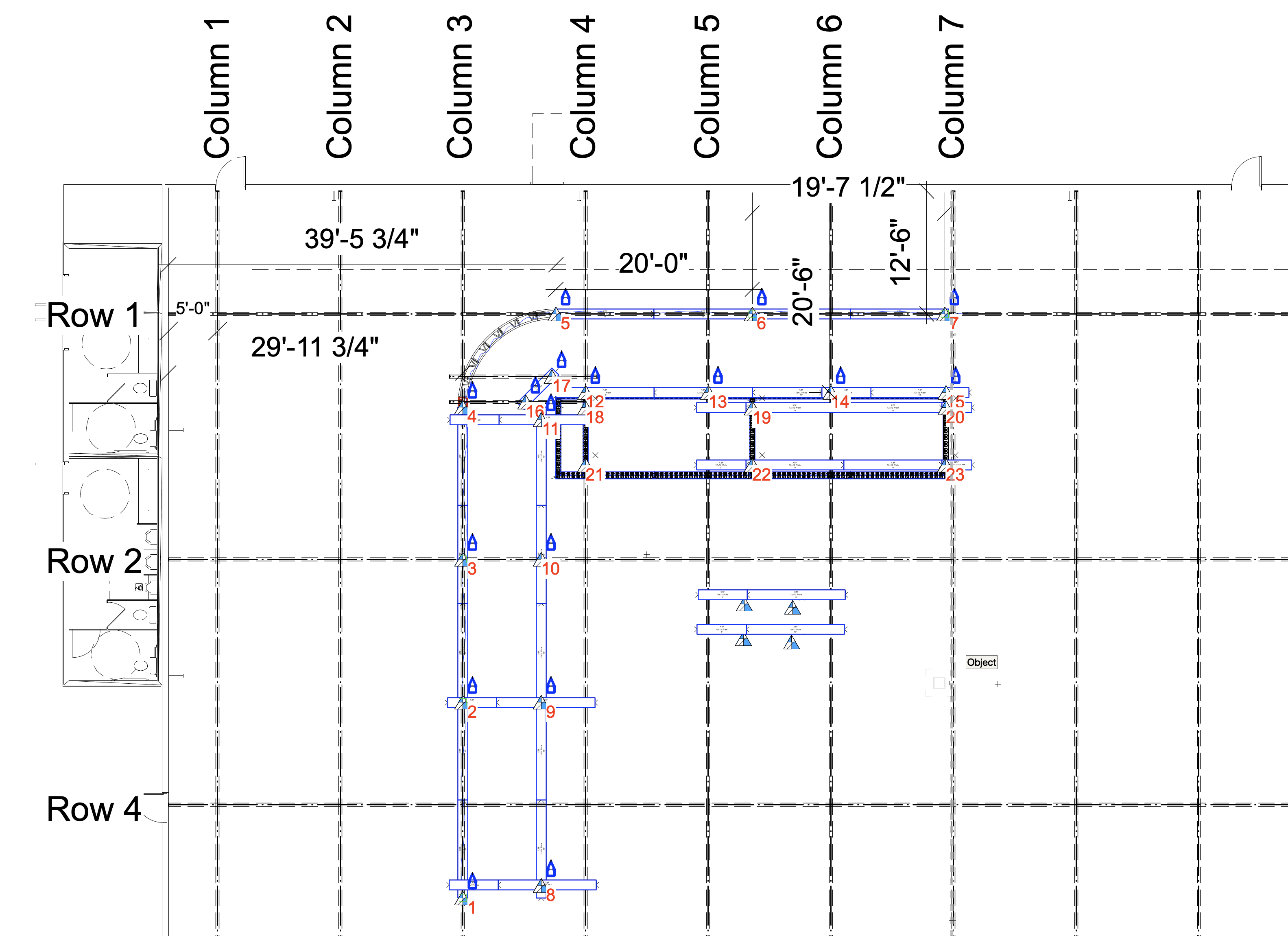
Drawing view with some measurements laid out for motors

Designing in 3D allows you to see if things will physically fit next to each other

I was able to visualize which hole I would need to pick from in the Mod Truss.

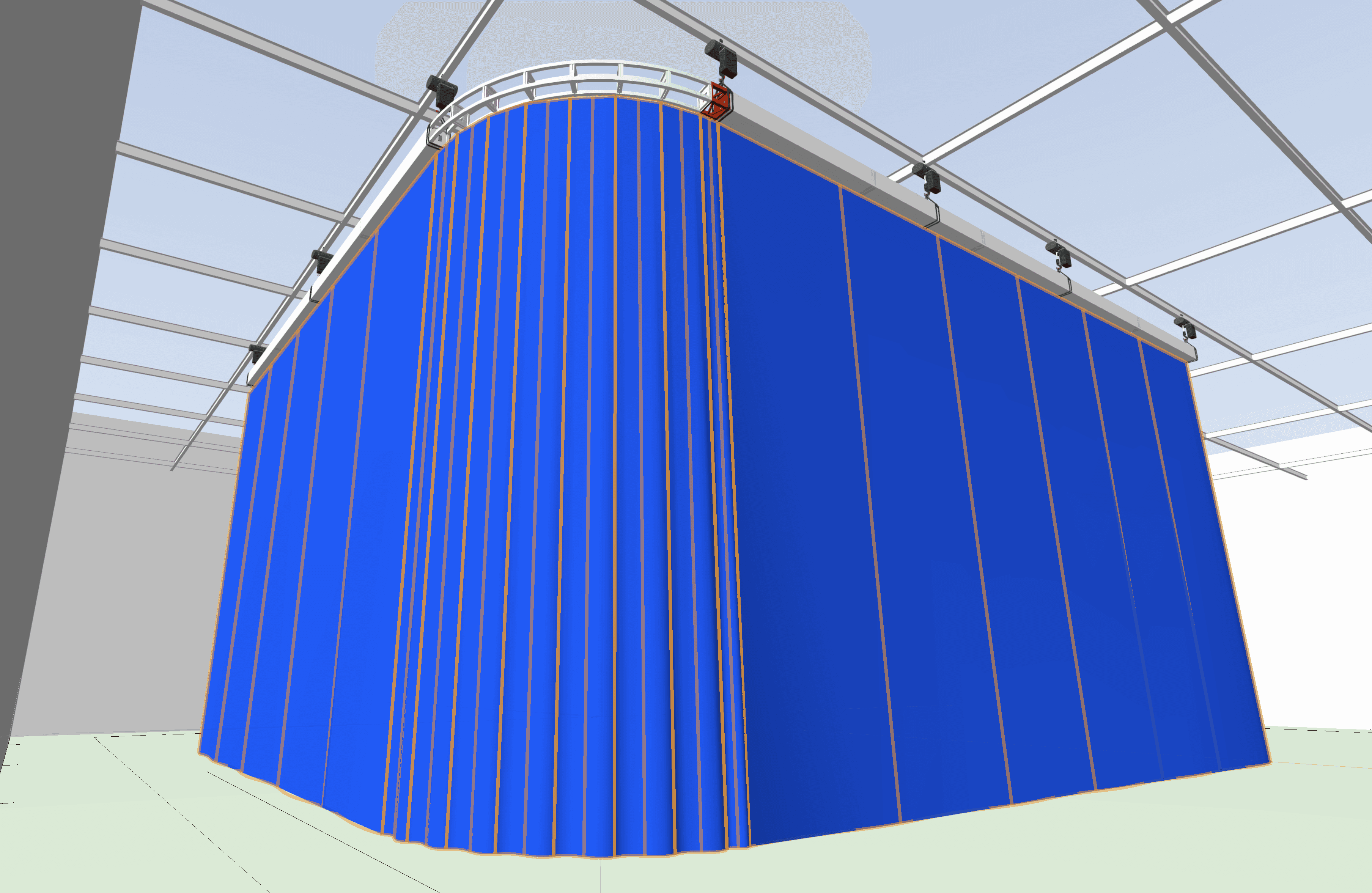
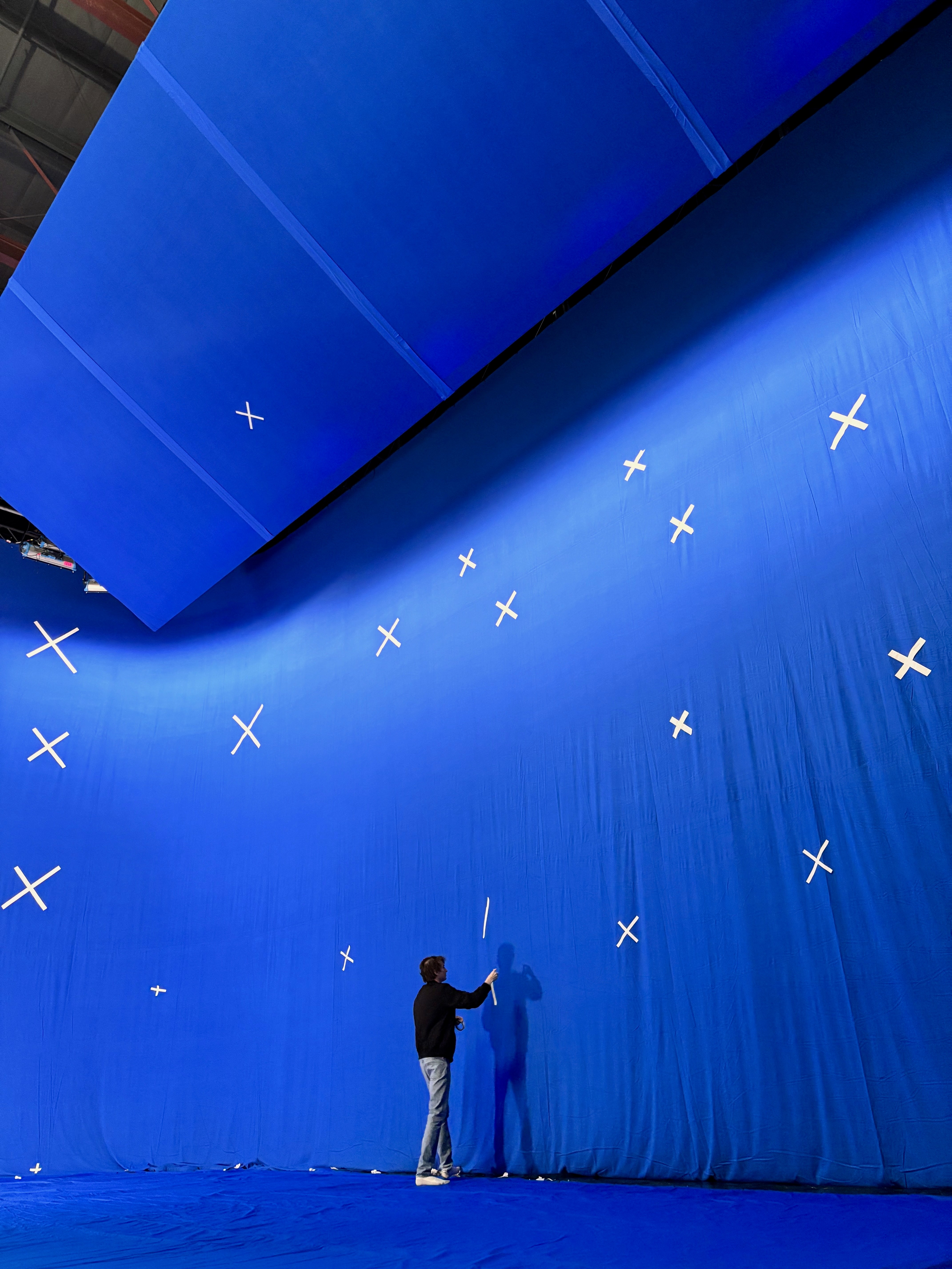
Curtain material helped visualize our bluescreen

by:

Brendan Riel

similar posts

similar posts

similar posts

project BTS

20x20 Telehandler Swatter

by:

Brendan Riel

20x20 12” box truss flyswatter on a JLG 1255 telehandler.

Ordered the swatter from SGPS Show Rig here in LA. They have a nice little package they send out which ensures you have everything you need. Their custom fork adaptors make assembly and attachment a breeze.

Used GAC flex, steel cable, and turnbuckles for the corner picks from the tower.

Overhead 20x20 1/2 soft frost diffusion in the swatter did most of the heavy lifting but we shaped up some negative fill on the ground and played around with a 12x green.

Finished off the day with some circle track in a field. J.L. Fisher Model 11 was our dolly of choice that day and we opted for skate wheels.

rig breakdown

Dolly ModX Camera Push

by:

Brendan Riel

Modulus-X offset dolly rig for pushing through car windshields and windows. Ran 12’ off the front and 8’ off the back. On the nose is a wedge plate with a dovetail to keep the rialto body super low profile. This is the dummy method where the tilt and pan are fixed. Mounted the venice body to the arm 9’ back and used minimal counterweight in the back. Truss and ModParts from Division.

project BTS

Pistachio Spec AD

by:

Aiden Oleskie

This was a spec ad for Wonderful Pistachios we did for a student class down at SCAD. It was a pretty big setup for a student spec, and lots of fun new stuff we did, like chroma screens, and car rigging.

project BTS

Pistachio Spec AD

by:

Aiden Oleskie

This was a spec ad for Wonderful Pistachios we did for a student class down at SCAD. It was a pretty big setup for a student spec, and lots of fun new stuff we did, like chroma screens, and car rigging.

project BTS

Pistachio Spec AD

by:

Aiden Oleskie

This was a spec ad for Wonderful Pistachios we did for a student class down at SCAD. It was a pretty big setup for a student spec, and lots of fun new stuff we did, like chroma screens, and car rigging.

project BTS

Pistachio Spec AD

by:

Aiden Oleskie

This was a spec ad for Wonderful Pistachios we did for a student class down at SCAD. It was a pretty big setup for a student spec, and lots of fun new stuff we did, like chroma screens, and car rigging.

rig breakdown

Overhead ModX Camera Rig

by:

Brendan Riel

Camera offset rig built out of Modulus-X Mx|66|. DP Scotty Uyeda wanted to get the camera out directly over the center of the couch. This 2nd story landing led to a spiral staircase but also provided the perfect space to set this rig on. This was a house in the hollywood hills and access wasn’t easy. We couldn’t quickly and efficiently bring a jib around the house and down to the room we were shooting in. We built the offset out of Modulus-X truss because we wanted customization for our measurements. A jib at this length would have required too much extension in the rear which would have interfered with a lighting fixture in the dining room.

Extension off the front: 12’6”

Website links

Upcoming

Shows

coming soon

Shop

coming soon

Podcast

coming soon

community

coming soon

Join our newsletter & stay up to date

By subscribing you agree to with our privacy policy and provide consent to receive updates from our company.

Legacy Grip 2025 All Rights Reserved

Website links

Upcoming

Shows

coming soon

Shop

coming soon

Podcast

coming soon

community

coming soon

Join our newsletter & stay up to date

By subscribing you agree to with our privacy policy and provide consent to receive updates from our company.

Legacy Grip 2025 All Rights Reserved

Website links

Upcoming

Shows

coming soon

Shop

coming soon

Podcast

coming soon

community

coming soon

Join our newsletter & stay up to date

By subscribing you agree to with our privacy policy and provide consent to receive updates from our company.

Legacy Grip 2025 All Rights Reserved

Website links

Upcoming

Shows

coming soon

Shop

coming soon

Podcast

coming soon

community

coming soon

Join our newsletter & stay up to date

By subscribing you agree to with our privacy policy and provide consent to receive updates from our company.

Legacy Grip 2025 All Rights Reserved